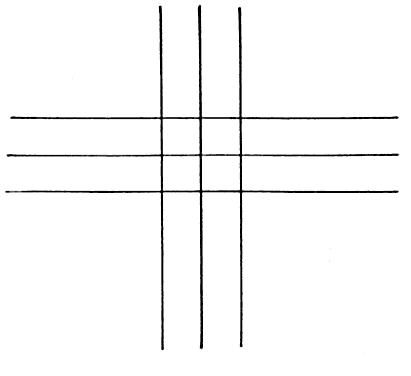
| The cross cylinder is particularly sensitive in assisting the patient in
the selection of the proper axis of his or her astigmatism. When the
cross cylinder straddles the presumed cylinder axis in the trial frame
in one position, it creates a new cylinder whose axis is approximately 40° away
from the original axis and increases the power of the
cylinder; however, in the other position, the axis will jump 40° in
the opposite direction but reduce the power. The patient easily perceives
this change, seeing the lower powered cylinder as clearer, and the
appropriate steps may be taken by the examiner. Many texts at this
point refer to the complexity of understanding the mathematics that show
why the foregoing occurs and pass onto another topic. With regard to the cross cylinder and axis determination, comprehending
the first paragraph is all you will need to be a successful refractionist. The
full power of the cylindric lens lies 90° from its axis. For
example, a + 1.00 D cyl × 180° has for its power at
the 180° meridian 0 D and at the 90° meridian + 1.00 D. What
may not be generally appreciated is that between these two meridians (180° and 90°) the lens has dioptric power. In the example
just mentioned, this begins with 0 D at 180° and increases at each
meridian to the maximum power, + 1.00 D at 90° (Fig. 1). Of course, this applies to any cylinder regardless of power, sign (plus
or minus), or axis. A cylinder will have a power of 0 D at its axis
and increasing plus or minus power at each meridian, reaching a maximum (i.e., the stated power of the cylinder) 90° from the axis. 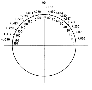 Fig. 1. + 1.00 D cyl × 180°. Power indicated at each 10° meridian. (Int Ophthalmol Clin 11:131, 1971) Fig. 1. + 1.00 D cyl × 180°. Power indicated at each 10° meridian. (Int Ophthalmol Clin 11:131, 1971)
|
The power at each meridian of the lens is a function of the sine of the
angle between the given meridian and the axis of the cylindric lens. To
review, the sine of an angle in a right triangle is determined by the
ratio between the length of the side opposite the angle and the length
of the hypotenuse of the triangle. For a given angle,  , it may be written as follows (Fig. 2). , it may be written as follows (Fig. 2). 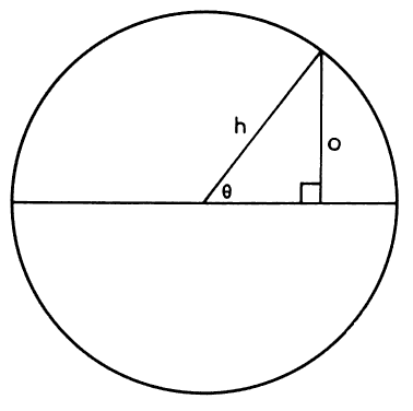 Fig. 2. Sine Fig. 2. Sine  equals side opposite given angle divided by the length of the hypotenuse. (Int Ophthalmol Clin 11:131, 1971) equals side opposite given angle divided by the length of the hypotenuse. (Int Ophthalmol Clin 11:131, 1971)
|

The sine of 0° is 0, the sine of 90° is 1, and the sine of 180° is
once again 0. Between 0° and 90°, the values of sine increase
from 0 to 1; they show a corresponding decrease between 90° and 180°. The
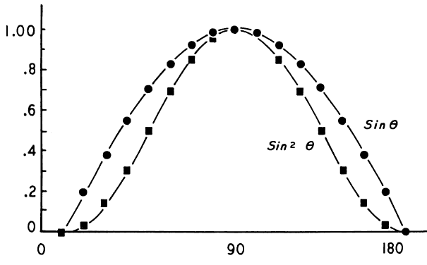
sines of angles from 0° to 180° may be plotted
on a graph, as shown in Figure 3 (the round points), and give rise to the sine curve. Many wavelike or
cyclic phenomena may be described by a sine curve. In our current example, the
changing powers of a cylindric lens seem to follow this curve. Two additional factors slightly complicate this discussion. First, the
relationship between the angle and the cylinder power is more accurately
described by the square of the sine. That is, Dm (the dioptric power
at any meridian of a cylindric lens) is equal to D (the maximum power
of the cylinder) multiplied by the sine squared of the given angle.8 This is written Dm = D sin2  . (The curve of sin2 . (The curve of sin2  is described by the square points in Figure 3.) Second, this formula is still only an approximation. The true values
for cylinder power are obtained through a more complex formula; however, the
values derived by the use of this approximate formula are accurate
enough for our purposes. is described by the square points in Figure 3.) Second, this formula is still only an approximation. The true values
for cylinder power are obtained through a more complex formula; however, the
values derived by the use of this approximate formula are accurate
enough for our purposes. If two cylinders of equal strength but opposite sign are placed one before
the other with axes superimposed, they will neutralize each other. For
example, if a -1.00 D cyl × 180° is placed before a + 1.00 D
cyl × 180°, the resultant power is zero. The -1.00 D, which
is the power in the vertical meridian of one lens, is neutralized
by the + 1.00 D in the same position in the other lens. In
addition, at each meridian between 0° and 180°, the powers present
are equal but of opposite sign, thus neutralizing each other as
well. If, however, the axes were not perfectly aligned, we would have to add, algebraically, the
powers present at each meridian and arrive at a resultant
power. For example, beginning with a cylinder + 1.00 D × 180°, as
pictured in Figure 1, we will superimpose a -1.00 D cyl but place its axis at 170° (10° “off
axis”) (Fig. 4). Note that at 90° in Figure 1, we have + 1.00 D; at 90° in Figure 4, we have -0.970 D. The resultant in this meridian is + 0.030 D; this
calculation is repeated at each 10° meridian. 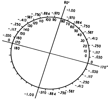 Fig. 4. -1.00 D cyl × 170°. Power indicated at each 10° meridian. (Int Ophthalmol Clin 11:131, 1971) Fig. 4. -1.00 D cyl × 170°. Power indicated at each 10° meridian. (Int Ophthalmol Clin 11:131, 1971)
|
The resultant is pictured in Figure 5. We have created a spherocylinder, the formula of which may be written + 0.174 D
sph -0.348 D cyl × 130°. Note the following: our -1.00 D cylinder
no longer neutralizes our + 1.00 D cylinder. A new cylinder has
been formed, in which the axis (using minus cylinder notation) is approximately 40° removed
from the axes with which we began (i.e., 180° and 170°). A small error in the placement of the axis of
the correcting cylinder produces a large displacement of the axis of
the resultant cylinder. -0.348 D cyl × 130°. Note the following: our -1.00 D cylinder
no longer neutralizes our + 1.00 D cylinder. A new cylinder has
been formed, in which the axis (using minus cylinder notation) is approximately 40° removed
from the axes with which we began (i.e., 180° and 170°). A small error in the placement of the axis of
the correcting cylinder produces a large displacement of the axis of
the resultant cylinder. 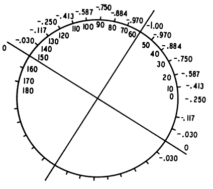 Fig. 5. + 0.174 D sph Fig. 5. + 0.174 D sph -0.348 D cyl × 130°. Resultant of superimposing Figures 1 and 4. (Int Ophthalmol Clin 11:131, 1971) -0.348 D cyl × 130°. Resultant of superimposing Figures 1 and 4. (Int Ophthalmol Clin 11:131, 1971)
|
Suppose the correcting cylinder were displaced by an even greater amount. Again, begin
with a + 1.00 D cyl × 180° and superimpose
a -1.00 D cyl, but this time displace the axis 30° (i.e., axis at 150°; Fig. 6). The resultant of this combination may be seen in Figure 7. The spherocylinder is + 0.50 D sph -1.00 D cyl × 120°. With the correcting cylinder equal in power
to the cylinder to be neutralized, an error in axis placement of 30° produces
a new astigmatism equal in power to the original cylinder. -1.00 D cyl × 120°. With the correcting cylinder equal in power
to the cylinder to be neutralized, an error in axis placement of 30° produces
a new astigmatism equal in power to the original cylinder. 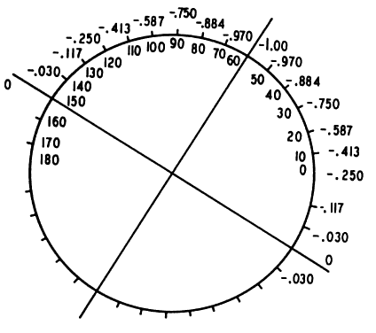 Fig. 6. -1.00 D cyl × 150°. Power is indicated at each 10° meridian. (Int Ophthalmol Clin 11:131, 1971) Fig. 6. -1.00 D cyl × 150°. Power is indicated at each 10° meridian. (Int Ophthalmol Clin 11:131, 1971)
|
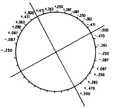 Fig. 7. + 0.50 D sph Fig. 7. + 0.50 D sph -1.00 D cyl × 120°. Resultant of super-imposing Figures 1 and 6 and adding the power at each meridian. (Int Ophthalmol Clin 11:131, 1971) -1.00 D cyl × 120°. Resultant of super-imposing Figures 1 and 6 and adding the power at each meridian. (Int Ophthalmol Clin 11:131, 1971)
|
The power of the resultant spherocylinder has increased from the previous
example (see Fig. 5), but the shift in the resultant cylinder axis is not much greater than
that produced by shifting the correcting cylinder 10° “off
axis.” By moving the correcting cylinder 20° farther off axis (from 170° to 150°), we have moved the resultant cylinder only 10° (from 130° to 120°). It can be shown that further
deviation of the correcting cylinder axis produces proportionately smaller
shifts in the resultant cylinder axis. The conclusion to be drawn
is that a small error in the placement of the correcting cylinder produces
almost maximal shifts of the resultant cylinder axis. (This large
shift in axis can be perceived by the patient and may be used in determining
the correct cylinder axis in refraction. This will be considered
in more detail later in the chapter.) Apply this knowledge to an actual refraction, using an eye that requires
a -1.00 D cyl × 180° for correction of ametropia. We have
shown previously that a -1.00 D cyl × 180° neutralizes a + 1.00 D
cyl × 180° in all meridians. Therefore, we may assume
the eye thus corrected contains a + 1.00 D cyl × 180°. That
is, it is 1.00 D myopic in the 90° meridian, with progressive
decrease in myopia to plano in the 180° meridian, and is corrected
by the -1.00 D cylinder. The refracting power of the eye is “too
strong” in the 90° meridian, and the image is in the
vitreous. This + 1.00 D cyl × 180° we can call the eye cylinder. It must have the same characteristics ascribed to cylindric lenses in
the previous section. If the correcting cylinder (-1.00 D cyl × 180°) is
precisely superimposed over the eye cylinder (+ 1.00 D × 180°) the
resultant is 0 D. If, however, the axis of the
correcting cylinder is displaced 10°, as in our previous example, the
resultant is a new cylinder, the axis of which is removed approximately 40° from
the true axis of astigmatism (see Fig. 5). If the error in the axis of the correcting cylinder is increased, the
further shift in the axis of the resultant astigmatism will be small
by comparison, as in our previous example in Figure 7. The new astigmatism produced by the improper placement of the correcting
cylinder axis we shall call secondary astigmatism. The data given in the previous section for two cylindric lenses applies
to the condition of a cylinder correcting an eye with astigmatism. We have now set the stage for understanding the use of the cross cylinder. In
considering the example given of a patient's eye with its
cylinder of + 1.00 D × 180°, if we assume that this eye
cylinder axis is actually at 170° and place our -1.00 D correcting
cylinder before the eye at this axis, a secondary astigmatism is created. (This
has been previously considered in detail in this chapter.) It
is this secondary astigmatism that is actually examined with the cross
cylinder. The cross cylinder is placed in front of the correcting
cylinder so that its axes straddle the axis of the correcting cylinder
at 45° each. (I have chosen a + 0.25 D cyl -0.25 D cyl for our example.) The cross cylinder is twirled, presenting
each of the two sides to the patient and thus reversing the positions
of the plus and minus axes. Figure 5 diagrams the secondary astigmatism. Figure 8 represents a 0.25-D cross cylinder, axes straddling 170°; the minus
axis is marked as a double line. If we superimpose Figures 5 and 8 and add the powers at each meridian, we arrive at Figure 9, which represents the approximate tertiary astigmatism produced with the cross cylinder in the following position: + 0.420 D
sph -0.25 D cyl for our example.) The cross cylinder is twirled, presenting
each of the two sides to the patient and thus reversing the positions
of the plus and minus axes. Figure 5 diagrams the secondary astigmatism. Figure 8 represents a 0.25-D cross cylinder, axes straddling 170°; the minus
axis is marked as a double line. If we superimpose Figures 5 and 8 and add the powers at each meridian, we arrive at Figure 9, which represents the approximate tertiary astigmatism produced with the cross cylinder in the following position: + 0.420 D
sph -0.840 D cyl × 130°. -0.840 D cyl × 130°. 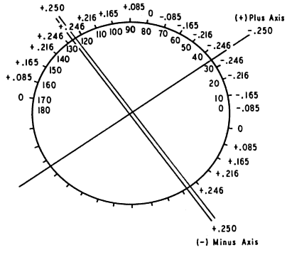 Fig. 8. The 0.25-D cross cylinder. Minus axis is a double line. Power is indicated
at each 10° meridian. Axes straddle 170° meridian. (Int Ophthalmol Clin 11:131, 1971) Fig. 8. The 0.25-D cross cylinder. Minus axis is a double line. Power is indicated
at each 10° meridian. Axes straddle 170° meridian. (Int Ophthalmol Clin 11:131, 1971)
|
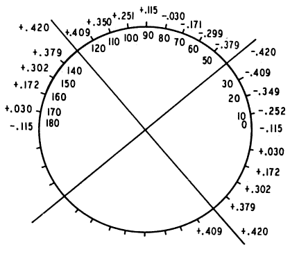 Fig. 9. + 0.420 D sph Fig. 9. + 0.420 D sph -0.840 D cyl × 130°. Resultant of superimposing Figure 5 (secondary astigmatism) and Figure 8 (cross cylinder with minus axis farther from 180°). (Int Ophthalmol Clin 11:131, 1971) -0.840 D cyl × 130°. Resultant of superimposing Figure 5 (secondary astigmatism) and Figure 8 (cross cylinder with minus axis farther from 180°). (Int Ophthalmol Clin 11:131, 1971)
|
Figure 10 shows the cross cylinder in the second position with axes reversed; the
minus cylinder axis is represented by a double line. Superimposing Figure 5 (the secondary astigmatism) and Figure 10 yields Figure 11, the tertiary astigmatism produced with the cross cylinder in the following
position: + 0.083 D sph -0.166 D cyl × 30°. Notice that in the second position of the
cross cylinder, the powers seem to neutralize each other at each meridian, whereas
in the first position they augment each other. The patient
will readily choose the position of the cross cylinder that produces
the weaker tertiary astigmatism as being less distorting or clearer. This
is the position of the cross cylinder depicted in Figure 10. Rotating the axis of the correcting cylinder toward the minus axis of
the cross cylinder will bring the correcting cylinder axis closer to 180°. This
is the reason for the following rule: “The correcting
cylinder is rotated toward the axis of the cross cylinder of similar
sign in the clearer position.” If a plus cylinder were used
for correction, the cylinder would be rotated toward the plus axis of
the cross cylinder; similar results would be obtained. -0.166 D cyl × 30°. Notice that in the second position of the
cross cylinder, the powers seem to neutralize each other at each meridian, whereas
in the first position they augment each other. The patient
will readily choose the position of the cross cylinder that produces
the weaker tertiary astigmatism as being less distorting or clearer. This
is the position of the cross cylinder depicted in Figure 10. Rotating the axis of the correcting cylinder toward the minus axis of
the cross cylinder will bring the correcting cylinder axis closer to 180°. This
is the reason for the following rule: “The correcting
cylinder is rotated toward the axis of the cross cylinder of similar
sign in the clearer position.” If a plus cylinder were used
for correction, the cylinder would be rotated toward the plus axis of
the cross cylinder; similar results would be obtained. 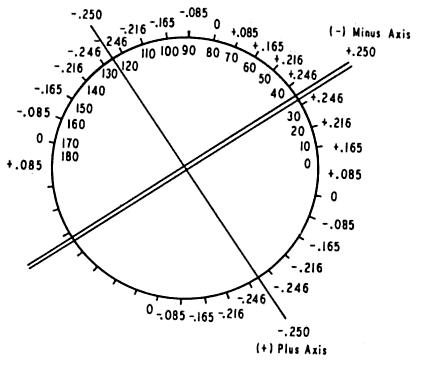 Fig. 10. The 0.25-D cross cylinder with axes reversed from positions in Figure 8. Minus axis is marked as a double line. Axes straddle 170° meridian. (Int Ophthalmol Clin 11:131, 1971) Fig. 10. The 0.25-D cross cylinder with axes reversed from positions in Figure 8. Minus axis is marked as a double line. Axes straddle 170° meridian. (Int Ophthalmol Clin 11:131, 1971)
|
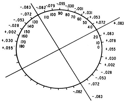 Fig. 11. + 0.083 D sph Fig. 11. + 0.083 D sph -0.166 D cyl × 30°. Resultant of superimposing Figure 5 (secondary astigmatism) and Figure 10 (cross cylinder with minus axis closer to 180°). Compare with Figure 9. (Int Ophthalmol Clin 11:131, 1971) -0.166 D cyl × 30°. Resultant of superimposing Figure 5 (secondary astigmatism) and Figure 10 (cross cylinder with minus axis closer to 180°). Compare with Figure 9. (Int Ophthalmol Clin 11:131, 1971)
|
When the correcting cylinder arrives at 180° the secondary astigmatism
disappears. The cross cylinder itself now forms a secondary astigmatism
as it straddles the axis of the correcting cylinder (which is now
at the correct axis). When the blurring produced in the two positions
of the cross cylinder is equal, the end point is established. Notice
that the cross cylinder produces little shift in the axis of the secondary
astigmatism. It instead augments the power of the tertiary astigmatism
produced in one position and diminishes it in another. In summary, we have done two things: - By misplacing the axis of the correcting cylinder, we have created a secondary
astigmatism.
- By using the cross cylinder, we have augmented or diminished the power
of this new astigmatism in order to ascertain which direction the correcting
cylinder must be rotated to approach the true axis of astigmatism.
You may wonder why we become involved with “tertiary astigmatism” when
we might use the blurring induced by the secondary astigmatism
to determine the correct axis. The following method may be used3: - Make a temporary overcorrection with the trial cylinder.
- Rotate the trial cylinder in the frame a few degrees to either side of
the assumed axis.
- Ask the patient to choose the clearer position; he or she will readily
recognize the sudden shift in the resultant cylinder axis as the correct
axis is passed, forming a secondary astigmatism.
There are, however, pitfalls to this procedure.8 The examiner must closely approximate the necessary cylindric power. Performing
this test with a slight overcorrection is desirable to enhance
the end point. If too strong a cylinder is employed, the degree the
cylinder must be rotated in order to achieve a significant shift in axis
is increased. This will reduce the power of the resultant cylinder, negating
somewhat the crisp end point of the test. If too weak a cylinder
is employed, the shift in axis with rotation of the correcting cylinder
will not be sufficient to make the test results definitive. Linksz8 found this rotation method far more accurate with the Reagan-Lancaster
dial than with Snellen letters. Rotation of the correcting cylinder before the eye to determine the correct
axis of astigmatism is highly accurate when the correct or slightly
stronger cylinder power is selected as the trial lens and the Reagan-Lancaster
dial is used as the test target. No similar reservations need
be made regarding the use of the cross cylinder in determining the
astigmatic axis. It is a highly accurate and reproducible technique. |  -8.00 D cyl.
 -0.12 D cyl × 180°
 -0.25 D cyl × 180°
 -0.50 D cyl × 180°
 -1.00 D cyl × 180°
 , it may be written as follows (



 -0.348 D cyl × 130°. Resultant of superimposing


