Chapter 70 The Optics of Wavefront Technology JIM SCHWIEGERLING Table Of Contents |
OUTGOING VERSUS INGOING ABERROMETRY TECHNIQUES FOR ABERRATION MEASUREMENT IN THE EYE SERIES MEASUREMENTS AND PARALLEL MEASUREMENTS IN ABERROMETRY APPLICATIONS OF WAVEFRONT TECHNOLOGY REFERENCES |
Wavefront technology has undergone an explosive development in recent years
and continues to be one of the most rapidly developing technologies
in ophthalmic research. The primary driving force behind this rapid
development is the refractive surgery industry, which is pushing toward
the goal of improved visual performance following surgery. There are
at least six commercially available systems for measuring wavefront
errors in the eye, with alternative technologies emerging as early research
prototypes. These systems are based on a variety of techniques for
measuring wavefronts. The objective of these devices is to enable the
ophthalmic practitioner to provide improved correction of the refractive
state of the eye and possibly improved diagnoses through superior
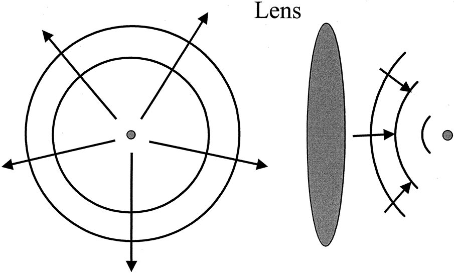
retinal imaging. Most imaging systems, including the eye, are designed to take points of light out in the world and relay them to a perfect focus on an image plane. To accomplish this task, the imaging system must convert the shape of wavefronts. Figure 1 illustrates a typical imaging system. A point of light gives off a series of expanding spherical wavefronts. These wavefronts propagate outward and are intercepted by the lens. The lens is designed to convert the expanding wavefronts into converging wavefronts that focus to a point. If the point of light is far from the lens, the wavefronts impinging on the lens have expanded to such a degree that they are perfectly flat plane waves. In terms of the eye, the ideal performance is that plane waves from a distant point are converted to perfectly spherical waves that converge to a point on the retina. For points closer to the eye, ideally the eye accommodates to convert the diverging wavefronts from the near object into perfectly spherical wavefronts that focus to a point on the retina.
All optical systems, including the eye, suffer from aberrations. Aberrations are errors introduced by the optical system that cause the perfectly spherical converging wavefronts to distort from their ideal shape, ultimately causing an imperfect focus. Eye care providers are familiar with some of the basic aberrations, but may be less familiar with the more complex aberrations. Basic aberrations (or low-order aberrations) include spherical refractive error, also known as defocus in the wavefront world, and astigmatism. These aberrations of the eye cause the wavefronts within the eye to deviate from their ideal shape. In the case of myopia, the converging wavefronts focus too quickly, converging to a point in front of the retina. In the case of hyperopia, the wavefronts do not converge rapidly enough, and the focus ends up behind the retina. In the case of astigmatism, the focus of the wavefront depends on meridian. There are two reasons these aberrations are familiar to practitioners. First, refractive error and astigmatism cause the bulk of the degradation in visual performance in the general population. Second, there are practical means for which to correct these errors (i.e., spectacles and contact lenses). However, more complex aberration types exist in the eye. These types are known as higher-order aberrations. The higher-order aberrations are what limit visual acuity to about 20/20 even with the correction of spherical and cylindrical refractive error. The goal of wavefront technology is to measure the aberrations of the eye. By measuring the aberrations of an individual eye, a custom correction based on the individual's aberration structure can be defined. Whereas many of the techniques for measuring wavefront aberrations have existed for a long time, the recent explosion in wavefront technology has occurred because the means for correcting these aberrations on an individual basis now exist in the form of scanning refractive surgery lasers and optometric lathes that can cut nonrotationally symmetric surfaces. These new custom corrections promise to improve visual performance better than conventional modes of correction. Measurement of wavefront aberrations is called wavefront sensing or aberrometry. This chapter outlines the different classes of aberrometers and reviews four commercially available techniques for performing wavefront sensing: the Shack-Hartmann technique, the Tscherning technique, retinal raytracing, and the spatially resolved refractometer. The advantages and disadvantages of the techniques are compared. Finally, applications of the wavefront sensors are described. |
OUTGOING VERSUS INGOING ABERROMETRY | ||
Aberrometers fall into two main classes: outgoing and ingoing. Outgoing
aberrometers operate by placing a point source of light on the retina
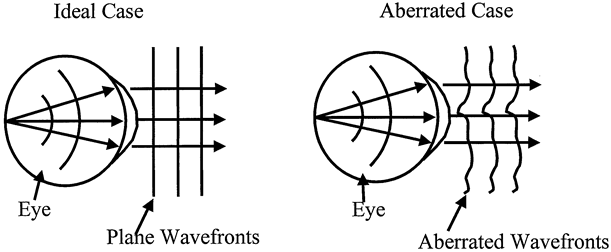
and determining the shape of the wavefront emerging from the eye (Fig. 2). A point source of light on the retina emits diverging spherical
wavefronts that pass through the crystalline lens and the cornea to exit
the eye. A perfect eye would not introduce any aberrations into the
wavefront, and perfectly planar wavefronts would emerge from the eye. However, if
the optics of the eye introduce aberrations, the emerging
wavefronts deviate from the ideal planar shape. Outgoing aberrometers
operate on the principal of the reversibility of light. If a point source
on the retina results in plane waves emanating from the eye, then
plane waves incident on the eye will focus to a perfect point on the
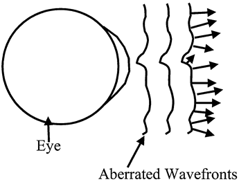
retina. Outgoing aberrometers typically measure the slope or direction
of travel of the wavefront (Fig. 3). The arrows in Figure 3 show the local direction of travel of the aberrated wavefront. Outgoing
aberrometers measure the directions of these arrows at a series of points
across the pupil of the eye and use this information to reconstruct
the shape of the wavefront.
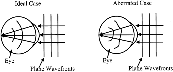
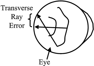
Ingoing aberrometers operate by examining how wavefronts external to the eye are altered as they pass through the optics of the eye (Fig. 4). In the case where no aberrations are present, plane wavefronts incident on the eye are converted to perfectly spherical wavefronts and converge to a point on the retina. When aberrations are introduced by the optics of the eye, the converging wavefronts are no longer spherical and a blurry spot is formed on the retina. As shown in Figure 5, ingoing aberrometers typically measure the transverse ray error. In other words, in the ideal case, a ray of light entering the eye focuses to the fovea. When aberrations are present, the ray strikes the retina at a point away from the fovea. Ingoing aberrometers measure the distance between the fovea and the point where the ray strikes the retina. This distance is proportional to the slope of the wavefront and can ultimately be used to reconstruct the shape of the wavefront.
|
TECHNIQUES FOR ABERRATION MEASUREMENT IN THE EYE |
A variety of techniques can be used to measure the aberrations of the eye. Four
methods have found their way into commercial products and are
discussed in detail. The origins of the techniques are fairly old, but
the development of new surgical and manufacturing techniques has brought
the methods into modern and automated systems that can rapidly and
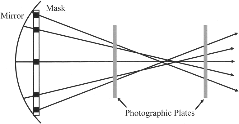
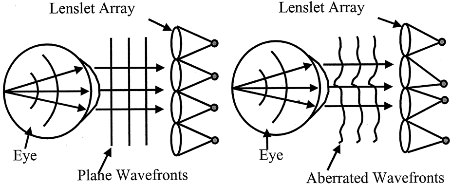
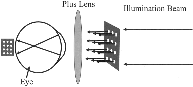
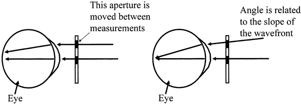
accurately measure the aberrations of the eye. SHACK-HARTMANN TECHNIQUE The Shack-Hartmann technique is an evolution of the Hartmann screen test. Platt and Shack give an excellent review of the history behind this technique and its application to the eye.1 The Hartmann screen test was employed in the early 1900s to test the quality of large astronomic telescope mirrors.2,3 In this test, a wooden board with a series of holes is placed over the surface of a telescope mirror (Fig. 6). The wooden board acts as a mask that takes light from a distant point, creating individual pencils of light on reflection from the mirror. These pencils converge toward the mirror focus. Photographic plates are inserted on either side of the focus to record the pattern of spots created by the pencils. Knowing the separation between the photographic plates and the positions of the spots on the plate allows for rays to be drawn between the two plates. High-quality mirrors have rays that all cross at the same point, whereas poor-quality mirrors have rays that cross the axis of the mirror at all different points, as shown in Figure 6. In the late 1960s, Shack and his colleagues developed the modern day version of the Shack-Hartmann sensor.4 The original application of the technology was to measure the aberrations caused by atmospheric turbulence to improve the quality of observation from ground-based telescopes. In the modern-day system, Shack replaced the mask with an array of tiny lenses to improve light-gathering capacity and to record wavefront slope directly. In the early 1990s, Liang and colleagues5 applied the Shack-Hartmann technique to the eye, and it is this configuration that makes up most of the commercially available systems (Fig 7). The Shack-Hartmann system is an example of outgoing aberrometry. A narrow beam of light is directed into the eye and forms a small point of light on the retina. This light scatters off the retina and emanates out of the eye. A lenslet array intercepts the emerging wavefront. In the aberration-free case, shown on the left in Figure 7, plane wavefronts emerge from the eye. Each tiny lenslet intercepts a portion of the wavefront that is flat and is traveling in the direction of the axis of the lenslet. The lenslet focuses the light down to a point, and the result is a grid of uniformly spaced spots at the back focal points of the lenslets. In the aberrated case, shown on the right in Figure 7, the emerging wavefront is no longer planar, but instead takes on a complex shape. Each individual lenslet in this case intercepts a small portion of the aberrated wavefront that is approximately planar over the aperture of the lenslet. However, the wavefront can be tilted with respect to the lenslet axis. The light will still focus to the rear focal plane of the lenslet, but the spot location will be shifted because of the wavefront tilt. The resulting spot pattern for an aberrated wavefront is a distorted grid of spots. By comparing the deviation in spot locations between the aberrated and the ideal wavefronts, the wavefront slope and ultimately the wavefront shape can be recovered. TSCHERNING TECHNIQUE The Tscherning technique dates back to the late 1800s.6 Tscherning placed a grid of equally spaced lines over a +5.00 diopter lens. Subjects viewing a distant point source through the lens perceived a distorted shadow of the grid on their retinas. By drawing the distorted grid, an analysis of individual wavefront aberrations could be performed. Howland and Howland7 later modified this subjective technique using a crossed cylinder in place of the plus lens to facilitate viewing and analysis. Walsh and colleagues8 further improved on the technique by photographing the distorted pattern on the retinas of their subjects, thus transforming the test into an objective method. Finally, the modern version of this technology, which has been adapted to a commercially available system, was described by Mierdel and coworkers9 and Mrochen and colleagues.10 Tscherning aberrometry is an example of ingoing aberrometry. Figure 8 shows the modern-day adaptation of the Tscherning aberroscope. In this system, a collimated beam of laser light is passed through a mask with a regular array of holes. The effect of the mask is to create a series of discrete collimated pencils of light. Normally, collimated light entering the emmetropic eye would focus to a point on the retina. However, a plus lens is added in the Tscherning aberrometer to effectively make the eye myopic. This added power causes the collimated beams to go through focus and then spread out again prior to striking the retina. As a result, a projection or shadow of the mask is formed on the retina. Aberrations from the ocular surfaces cause a distortion in the spacing between the “holes” in the shadow. The Tscherning aberrometer is essentially the Hartmann screen test applied to the eye. A fundus camera (not shown in Figure 8) is then used to capture an image of the shadow formed on the retina. The distortion in the hole pattern is related to the transverse ray error of the wavefront, which can ultimately be used to reconstruct the shape of the aberrated wavefront within the eye. The Tscherning technique is an ingoing type of aberrometry because the aberrations of the eye distort the shape of the grid as the light goes into the eye. To capture the shape of this ingoing distortion, an external camera must be used to photograph the pattern. Since the camera records light coming out of the eye, it may be tempting to call the Tscherning technique an outgoing technique. However, this is not the case. The aberrations of the eye do affect the grid image, but on the way out; the grid is simply blurred. The spacings between the points in the grid remain unchanged on the way out. In this manner, the Tscherning technique separates the aberrations of the eye on the way in and the aberrations on the way out. RETINAL RAYTRACING TECHNIQUE Retinal raytracing is another example of ingoing aberrometry that was developed by the Institute of Biomedical Engineering, Kiev, Ukraine.11 It works on the same principal as the Tscherning aberrometer. However, instead of using a mask with an array of holes, a single beam is directed into the eye. A measurement of the intersection of this beam with the retina is made. The transverse ray error can be calculated from this intersection. The spot is then scanned to a new entry location within the pupil, and the measurement process is repeated. By examining an array of entry points within the pupil, a map of the wavefront error within the eye can be calculated (Fig. 9). A narrow laser beam is directed into the eye so that it is parallel to the visual axis. Normally, this collimated beam would focus to a point on the fovea. However, aberrations in the eye cause the beam to deflect and strike the retina away from the fovea. An imaging system is then used to project the retinal spot onto a position sensor. This sensor records the position of the beam relative to the fovea, which gives the transverse ray error for a particular pupil entry point. The input beam is scanned across the pupil to determine the transverse ray error for an array of pupil locations, and this information is used to reconstruct the wavefront error of the eye. Rapid-scanning and position-sensing technology is required with this technique to ensure that eye motion effects are negligible. SPATIALLY RESOLVED REFRACTOMETRY TECHNIQUE The spatially resolved refractometer is based on the 400-year-old work of a Jesuit priest named Christopher Scheiner.12 The Scheiner disk is a mask with two small holes. An observer views a distant point source through the mask. In an aberration-free eye, the light passing through the mask and entering the eye at two separate pupil locations would come to focus at the same point on the retina. However, in the presence of aberrations, the spots on the retina do not coincide. The separation of these spots is related to the transverse ray error. Smirnov13 demonstrated that the Scheiner disk could be used to measure the wavefront aberrations of the eye. Figure 10 illustrates the modifications made by Smirnov to the Scheiner principle. If two parallel beams are directed into the eye of a subject at two different pupil locations, the Scheiner principle says that in the presence of aberrations, in general, two separate spots will be perceived by the subject. If one of the beams enters the eye at a specific angle, the spots will appear to merge. The angle of this beam is related to the slope of the external wavefront; therefore, spatially resolved refractometry is an example of outgoing aberrometry. Smirnov devised a psychophysical test in which one beam enters the center of the subject's pupil parallel to the visual axis and a second beam enters the eye at a peripheral pupil location. The subject tilts the peripheral beam to make the spots he or she perceives coincide. The angle of the incident beam is recorded, and the process is repeated for an array of pupil entry locations. Webb and colleagues14 built the modern version of this system. Since the system is based on a psychophysical test, it incorporates the subjects' perceptions, whereas the previously described aberrometers do not take the subjects into account. However, this is also a drawback: Because the test requires the interaction of the subject, it takes several minutes to perform a sufficient sampling of pupil entry positions. |
SERIES MEASUREMENTS AND PARALLEL MEASUREMENTS IN ABERROMETRY |
The preceding wavefront technologies take two separate approaches to measuring
aberrations. The Shack-Hartmann and the Tscherning devices
measure wavefront aberrations in parallel, meaning that many different pupil entry positions are measured simultaneously. The
retinal raytracing and spatially resolved refractometer
techniques, conversely, measure in series, meaning that a single pupil entry point is measured in a given instant
and measurements at different pupil entry points are made sequentially. The advantage of parallel measurement is that hundreds of points can be captured at the same time to avoid errors caused by eye motion and fluctuations in tear film and accommodation. Typically, measurements with the Shack-Hartmann and Tscherning systems can be made in a single video frame, which is equivalent to 25 to 30 milliseconds. The retinal raytracing system operates on the order of 50 milliseconds for 64 pupil points. The spatially resolved refractometer operates on the order of several minutes for 36 pupil points. The drawback to systems that measure in parallel is that there is a limit to how densely measurements can be made within the pupil. In the Shack-Hartmann system, fabrication of the lenslet array is the limiting factor. As the diameter of the lenslets decreases, the cost of fabrication of the lenslet arrays increases dramatically. The lower limit for lenslet arrays found today is around 200 μm between each lenslet. In the Tscherning system, the limitation on sampling the pupil is determined by the spacing of spots on the retina that can be reliably resolved. The advantage of systems that measure wavefront aberrations in series is that the number of samples within the pupil and the measurement region within the pupil are customizable. Thus, the pupil can be sampled with arbitrary resolution. If a patient has a high level of aberration in a localized region of the pupil, the series system can focus on and perform high-resolution measurement of this region. The drawback to these systems is that as the number of measurement points increases, so does the duration of the examination. |
APPLICATIONS OF WAVEFRONT TECHNOLOGY | ||
Aberrometers provide the shape of the wavefront for an individual patient. This
information is sufficient to create a theoretical correction
for the patient that will optimize his or her vision. The wavefront data
carry not only information pertaining to the patient's required
sphere and cylinder correction, but also the fine variations in visual
structure that have been termed irregular astigmatism. Irregular astigmatism is any additional refractive error that cannot
be eliminated with conventional spherocylindrical correction. Irregular
astigmatism is simply the higher-order aberrations of an individual
patient. Wavefront technology provides the means to rapidly measure
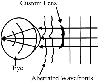
these aberrations and to define the perfect correction for each patient (Fig. 11). A custom correction converts a planar wavefront from a distant
object into a wavefront that matches the wavefront measured by the aberrometer. In
this manner, the custom correction modifies the wavefront
so that it perfectly compensates for the aberration introduced by the
optics of the eye. The result, in theory, provides diffraction-limited
performance and could lead to visual acuity around 20/8.15
Researchers at the University of Rochester demonstrated the potential of customized correction of aberrations in the eye.16 They used an adaptive optics mirror to compensate for the aberrations in individual eyes. Adaptive optics mirrors are mirrors that can locally be deformed by actuators pushing on the back of the mirror. The resultant deformations can take on complex shapes to correct for aberrations in the eye. By linking the mirror to an aberrometer, the aberrations of the eye can be systematically nullified. Figure 12 demonstrates the adaptive optics setup for testing the benefits of custom correction. In visual acuity testing, the Rochester group found that subjects with an acuity of 20/20 could be taken to an acuity of 20/10. In measuring contrast sensitivity, the researchers found a two- to threefold increase when the adaptive optics mirror was employed. These benefits demonstrate that custom correction can provide visual performance enhancement. Several applications of wavefront technology that take advantage of the information provided by aberrometers are discussed below.
CUSTOM REFRACTIVE SURGERY Molebny and colleagues17 suggested that wavefront measurements could be used to increase the accuracy of excimer laser refractive surgery. The custom lens shown in Figure 11 is ablated directly into the corneal surface in an excimer laser refractive surgery procedure. Obviously, registration of the pattern is important. Furthermore, small eye motions during the procedure can reduce the potential benefits of the custom surgery. To overcome these issues, fast eye trackers are used to appropriately impart the pattern into the cornea. Other issues affecting customized refractive surgery are the biomechanical changes that occur in the cornea. For instance, removing tissue from the cornea causes a peripheral bowing and subsequently a change in the aberration structure of the eye. Healing is also an important factor, since subtle features placed in the cornea to correct aberrations can be hidden by stromal and epithelial remodeling in the weeks and months following the procedure. Custom refractive surgery is emerging worldwide. Studies using the technology have demonstrated a major impact on the results of refractive surgery.18 Much of this impact has been from the bottom up. The number of patients achieving 20/20 vision following refractive procedures is dramatically higher than with conventional surgery, whereas a smaller but significant number of patients gain lines of acuity. This result suggests that the patients with larger degrees of aberration have the most to gain from customized technology. Patients who have already undergone conventional refractive surgery and have experienced a dramatic increase in their higher-order aberrations or decentered ablations may also benefit from the custom procedures.19 CUSTOM CONTACT LENSES Smirnov,13 following his pioneering work in measuring the aberrations of the eye, suggested that contact lenses could be manufactured that would correct for these errors. For custom contact lenses, the compensating aberration pattern is imparted to one or both surfaces of a contact lens. Custom contact lenses have become much more feasible with recent developments in lathe technology. Modern lathes can now employ a rapidly oscillating tool that allows nonrotationally symmetric surfaces to be cut into contact lens surfaces. One issue that arises with this technology, however, is the stability of the correction on the eye. Because the contact lens moves across the surface of the eye, there is only one location where the aberrations are corrected. A second concern with custom contact lenses is materials. Soft contact lens materials are far more positionally stable on the eye, but are typically made in a dehydrated state. Expansion of the material when hydrated must be well characterized to accurately incorporate the aberration correction into the lens. Rigid lenses do not expand on hydration and appear to be much more suitable for custom lenses. However, rigid lenses tend to drift and move on the cornea to a large degree. Much research is still needed in this area to determine the benefits of custom contact lenses. CUSTOM INTRAOCULAR LENSES Intraocular lenses may also benefit from wavefront correction. Currently, an aspheric intraocular lens is commercially available that corrects for some of the spherical aberrations in the average human eye. Whereas intraocular lenses have traditionally been prescribed for aphakic patients, phakic intraocular lenses are an emerging technology. Conceivably, either type of lens implant could be customized to correct for aberrations in an individual patient's eye. The difficulty with this customized technology is determining the patient's aberration structure prior to implantation so that an appropriate implant can be fabricated. Light-adjustable intraocular lenses may offer a solution for customized intraocular lenses.20 The shape of these lenses can be modified and permanently fixed following implantation. Therefore, the lens can be implanted and the eye allowed to heal and stabilize following surgery. Then, residual aberrations can be measured with the implant in place and the lens modified to correct them. Work on this type of implant is still in its early phase, but great potential exists for the technology. RETINAL IMAGING Aberration correction works in both directions. If aberrations are corrected in the eye, the practitioner can get an improved image of the retina. Liang and colleagues16 first used wavefront technology to improve the optical quality of fundus imaging. This work led to the first in vivo imaging of photoreceptors21 and in vivo classification of cone types.22 These studies further resulted in the development of a scanning laser ophthalmoscope that can image individual photoreceptors and overlying structures, such a capillaries.23 This technology promises to provide further information about the structure, function, and diseases of the retina, which until recently, were impossible to image in the living eye. CONCLUSION Wavefront technology is an exciting and rapidly developing area of ophthalmic research that will potentially benefit the visual performance of a large segment of the population. It also offers the potential for improved diagnoses of ocular and systemic conditions through improved viewing of structures and blood flow in the retina. Aberrometers are tools that will become more prevalent in the offices of eye care providers, much as corneal topographers have become widespread over the past 15 years. Whereas topographers opened up new insights into the optics of the cornea and its effect on visual performance, aberrometers provide information about the optics of the entire eye. Thus, interaction between the cornea and the crystalline lens can be assessed with this technology, with the long-term benefit of improved visual function for many patients. |