|
|
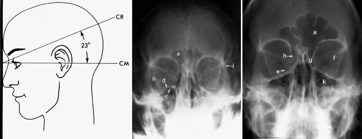
| Fig. 3. A. Schematic showing positioning for a Caldwell projection. (CM, canthomeatal line; CR, central ray) B. Radiograph of a Caldwell projection. The petrous ridge is positioned at the orbital floor. Detail of the orbital floor and maxillary sinus is blocked. C. The radiograph is taken at a steeper angle so the petrous ridge is now positioned lower within the maxillary antrum. (a, frontal sinus; b, innominate line; c, inferior orbital rim; d, posterior orbital floor; e, superior orbital fissure; f, greater wing of sphenoid;g, ethmoid sinus; h, medial orbital wall; i, petrous ridge; j, zygomatic-frontal suture; k, foramen rotundum) (A; Rao VM, Gonzalez CF: Plain film radiography and polytomography of the orbit. In Gonzalez CF, Becker MH, Flanagan JC [eds]: Diagnostic Imaging in Ophthalmology, pp 1–7. New York, Springer Verlag, 1986) |