Chapter 51A
Spectacle Lens Powers
GREGORY L. STEPHENS and JOHN K. DAVIS
Main Menu   Table Of Contents

Search

MYOPIA, HYPEROPIA, AND ASTIGMATISM
LENS POWER
SIGN CONVENTION
FOCAL POINTS AND FOCAL LENGTHS
EFFECTIVITY
SURFACE POWER
BACK VERTEX POWER
THE LENS CLOCK
THE BASE CURVE
COMPENSATED CURVES
SPHEROCYLINDER LENSES
HOW LENSES ARE SUPPLIED

The primary goal of a refractive examination is to discover the lens power that will result in a sharp image of a distant object being formed on a patient's retina when the patient is not accommodating. There may be other requirements, such as a need for clear vision when reading or when performing occupational tasks, but in this chapter we are concerned only with distant vision. With the correcting lens in position, parallel rays from a distant object entering the spectacle lens are either converged or diverged to compensate for the patient's refractive error. The patient then is able to see distant objects clearly and can accommodate or use multifocal lenses to see objects at other distances.

The word parallel is used in this chapter to describe a bundle of light rays coming from a single point on a distant object, at the point where the eye's line of sight intercepts the object. If an eye with a 7-mm diameter pupil looks at a road sign 100 m away, the bundle of rays that enter the eye from any single point on the sign have diverged only of a degree, so we call them parallel. In a refracting room, the rays from a single point on a letter on the visual acuity chart are not quite parallel. At 20 feet (6 m), the light rays have a divergent power of -0.16 diopters (D) as they enter the refractor. At 10 feet (3 m), the light rays diverge -0.33 D. Some doctors adjust for this factor when they determine the spectacle prescription.

Back to Top
MYOPIA, HYPEROPIA, AND ASTIGMATISM
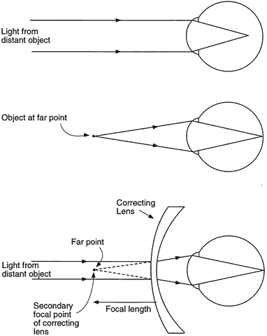
When an uncorrected myope looks at a distant object with accommodation relaxed, parallel light rays entering the eye form an image in front of the retina (Fig. 1). For the image to fall on the retina, the light entering the eye must therefore be made divergent. There are two ways to accomplish this objective. The object may be moved closer to the eye so that the object itself becomes a source of divergent light. The object position at which light from the object forms a focused image on the retina is the patient's far point (punctum remotum). Alternatively, if the object is to remain far away, at optical infinity (approximately 6 m), a divergent (minus power) lens may be placed in front of the eye to correct the refractive error. When the lens has the proper power, parallel light from the object is diverged so it appears to originate from the patient's far point. In the terminology of geometric optics, the lens forms a virtual image of the distant object at the patient's far point. This image becomes the object for the eye, which converges the light to form the image on the retina.

Fig. 1. Optical correction of myopia. Light from a distant object focuses in front of the retina of the uncorrected eye. For the image to fall on the retina, the object must be placed at the far point of the eye. Alternatively, a minus-power correcting lens may be placed in front of the eye to provide divergent light that simulates light coming from a near object. The secondary focal point of the correcting lens falls at the far point of the eye.

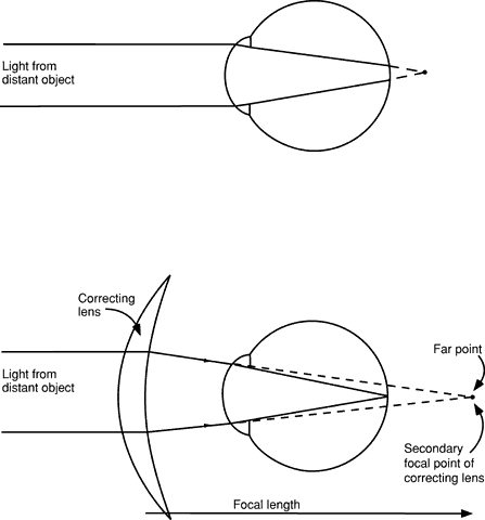
An analogous situation occurs for the uncorrected hyperope (Fig. 2). When the patient views a distant object without accommodating, the image falls behind the retina. Placing an image on the retina requires convergent light, a situation that cannot be achieved by moving the object, but only with a lens in front of the cornea or with accommodation. A convergent (plus power) lens placed in front of the eye converges the parallel light rays. This convergent light incident on the cornea is further converged by the cornea and lens to form a retinal image. Unlike the situation of the myope, the far point in the hyperope is a point behind the retina. A convex lens or accommodation converges the light from the distant object toward the far point so that the final image is formed by the eye on the retina. Young hyperopes who can bring the image onto the retina by accommodating may not seek a refractive correction until they get older and begin to lose their accommodative ability or until prolonged near work causes fatigue because of the prolonged accommodation required.

Fig. 2. Optical correction of hyperopia. Light from a distant object focuses behind the retina of the uncorrected eye. The focal point of the plus-power correcting lens must fall at the far point to correct the hyperopia.

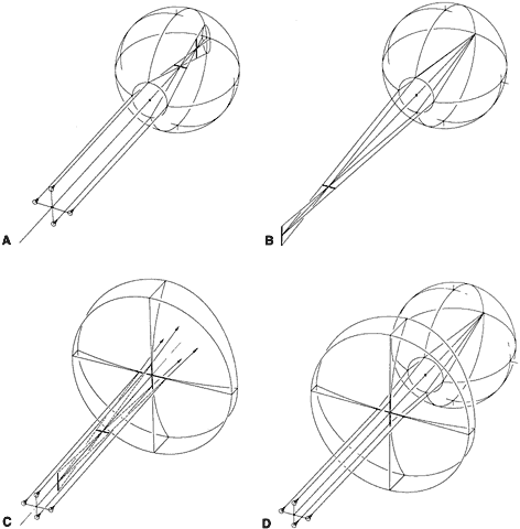
When a patient with astigmatism views a distant object point without accommodating, the point is imaged as two lines oriented 90 degrees apart (Fig. 3). In essence, the astigmatic eye has two different far points. (The astigmatism may be combined with either hyperopia or myopia.) Correction of the patient's refractive error now requires a lens that forms two different images, one at each of the far points. Such a lens has two different powers and is termed a spherocylinder, or toric, lens to distinguish it from a spherical, or sphere, lens, which corrects only myopia or hyperopia. With the proper spherocylinder lens in position, the distant point object can be focused as a single point image on the retina.

Fig. 3. Optical correction of astigmatism. A. Light from a distant point object is focused at two different positions by the astigmatic eye. The images of the point object are lines. B. The astigmatic eye has two far points, one for each principal meridian. For this myopic eye, the far points are in front of the eye. C. A spectacle lens that corrects astigmatism has two focal points. D. When the focal points of the correcting lens coincide with the far points of the astigmatic eye, the refractive error is corrected.

Back to Top
LENS POWER
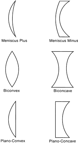
The power of a spectacle lens is obtained from a combination of the powers of its front and back surfaces. Each surface of a lens may be either convex, concave, or flat (plano or zero power), resulting in six general lens shapes (Fig. 4). Spectacle lenses used to correct refractive errors are almost always meniscus lenses, with both lens surfaces concave toward the eye. Plano-concave and biconcave shapes are used only for high minus power lenses. Biconvex and planoconvex shapes are not used for spectacle lenses because of their poor off-axis optical quality when mounted in a spectacle frame. However, with proper design and the use of aspheric surfaces, these lenses are useful as, for example, magnifying lenses (low-vision aids) and ophthalmoscopy lenses.

Fig. 4. Forms or shapes of lenses.

Back to Top
SIGN CONVENTION
The use of a sign convention for measurement of distances simplifies the calculation of lens power. One commonly used convention is to specify distances relative to the direction of travel of light. In this chapter, light is always considered to be traveling from left to right. If a distance is measured in the same direction as the direction of travel of light, then the distance is positive. If it is measured in the opposite direction of light, the distance is negative.
Back to Top
FOCAL POINTS AND FOCAL LENGTHS
As illustrated in Figures 1 and 2, the lens that corrects a refractive error images parallel light rays from a distant object. The point at which a lens brings parallel light to a focus is the secondary focal point of the lens, and the distance from the lens to the focal point is the focal length. The term secondary focal point is useful when discussing complex optical systems and instrument lenses. For clinicians, there is nothing secondary about the focal point for incident parallel light. It is the only focal point of interest. Some writers have called it the back focal point, and the distance from the back vertex or back surface of a lens to its back focal point is the back vertex focal length, usually expressed by the symbol fV. The reciprocal of this distance in meters is the back vertex power of the lens, D, which is measured in units of diopters. Back vertex power is the only power used by clinicians for spectacle lenses.

The position of the back focal point determines the sign of the lens power. In Figure 1, the back focus of the correcting lens is to the left of the lens back surface. The back vertex focal length, measured from the lens back surface to the back focal point, is opposite the direction of travel of the incident parallel light, so both the back vertex focal length and the lens power are negative. That is why this type of lens is termed a negative or minus lens. The back focus of the correcting lens in Figure 2 is to the right of the lens, the lens power is positive, and the lens is a plus lens. A spherocylinder lens has two powers, and each power may be either plus or minus. If the two powers properly correct the patient's refractive error, there is a single sharp point image on the retina for each point on the object.

Back to Top
EFFECTIVITY
When a refraction is performed on a patient, the refraction is correct only for the position of the lens that is placed in front of the eye. The position of the lens is specified by its vertex distance, the distance from the back surface of the lens to the apex of the patient's cornea. The patient's far point is located at the back focal point of the lens, which is located at a distance from the back surface of the correcting lens equal to the reciprocal of the lens power. When a spectacle lens is prescribed, the lens must be positioned in the patient's spectacle frame at the same vertex distance as for the refracting lens if the back focal point of the prescribed lens is to fall at the patient's far point. The effectiveness or effectivity of the prescribed lens and the refraction will then be the same.

If the spectacle lens prescribed for the patient is not positioned at the same vertex distance as that of the refracting lens, then the spectacle lens no longer corrects the patient's refractive error properly. The error in position of the back focal point relative to the patient's far point is equal to the error in vertex distance. A lens that has effectively the same power as that of the lens used in the refraction must be prescribed; that is, the prescribed lens must have a different power so that its back focal point once again coincides with the patient's far point. The new effective power or “effectivity” can be calculated as follows:

(1)


effective power = 1(fV + d)

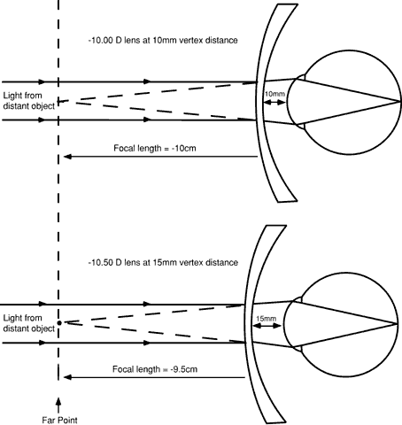
where fV is the back vertex focal length of the refracting lens and d is the difference in vertex distance of the two lenses, with both distances measured in meters. If the spectacle lens is fitted forward of the position of the refractor lens (at a longer vertex distance than that of the refractor lens), then d is positive. If the spectacle lens is closer to the eye than the refractor lens, d is negative. Figure 5 provides an example. A refraction has been performed on a patient, and a power of -10.00 D is found with the refractor at a vertex distance of 10 mm. This lens has a back vertex focal length of -10 cm, so the patient's far point is 10 cm in front of the lens back surface. If the patient will be wearing spectacles that position the lens at a vertex distance of 15 mm, the distance, d, is + 5 mm, and the spectacle lens power needed is 1/(-0.10 + 0.005), or -10.53 D (-10.50 D when rounded to the nearest 0.25 D).

Fig. 5. The principle of effectivity. The lens power needed to correct a refractive error depends on the vertex distance of the lens. A -10.00-D lens at a vertex distance of 10 mm corrects the refractive error because the back focal point of the lens falls at the far point of the eye (top). A lens positioned at a vertex distance of 15 mm must have a power of -10.50 D to correct the same refractive error (bottom).

A simple rule of thumb can be used to determine whether a vertex distance change is sufficient to require a change in the power of the lens ordered for a patient. The change in effectivity, or the change in lens power needed, is approximately equal to:

(2)


effectivity change = d × D2

where d is measured in meters and D is the lens power in diopters. Table 1 shows the results of this calculation for a displacement value (d) of 5 mm. Effective power changes are not significant for lower-power lenses. It is only for higher-power lenses and larger changes in lens position that the clinician must take effectivity changes into account.


TABLE 1. Effectivity for a 5-mm Vertex Distance Change


Lens power (D)3.004.005.006.007.008.009.0010.00
Effectivity change (D)0.040.080.120.180.250.320.400.50


Back to Top
SURFACE POWER
As previously mentioned, the power of a spectacle lens is determined by the powers of its front and back surfaces. The power of a lens surface is given by:

(3)


D = (n2- n1)r

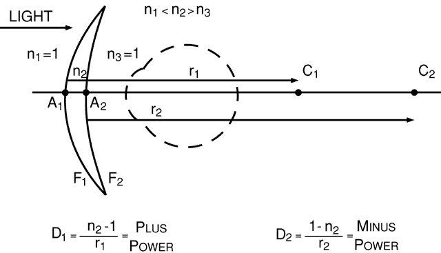
where D is the surface power in diopters, n1 is the index of refraction of the medium containing the incident light, n2 is the index of the medium containing the refracted light, and r is the radius of curvature of the surface, specified as the distance from the surface to its center of curvature, measured in meters. A sign convention similar to that used for focal lengths must be used for radii, and an example is shown in Figure 6. With light traveling from left to right, the distances ÜobA1C1 and ÜobA2C2 are both positive. The index of the lens is always greater than 1, so the front surface power (D1) is positive and the back surface power (D2) is negative, the typical surface power relationship for most spectacle lenses.

Fig. 6. A sign convention for lens surface power and radius of curvature. C1 and C2 are the centers of curvature of the front and back surfaces, respectively, of this meniscus lens. The points A1 and A2 mark the position of each surface. The distances measured from A1 to C1 and from A2 to C2 are both positive because both are measured in the direction of the incident light.

Back to Top
BACK VERTEX POWER
The power of a spectacle lens is not just the sum of its surface powers (D1 + D2). The clinician is interested in the power of a lens measured relative to the position of the lens back surface, which requires that the effectivity of the lens front surface be calculated at the lens back surface before the surface powers are added. We can treat the front surface as a thin plus-power lens displaced forward from the back surface by the thickness between the surfaces. The back vertex power (D) of the lens, the power of the lens calculated at the lens back surface, then becomes:

(4)


D = D11 - tn D1 + D2

where D1 and D2 are the lens surface powers, t is the center thickness of the lens in meters, and n is the index of refraction of the lens material. The t/n term is analogous to the displacement d in the effectivity formula (equation 1). The displacement in an optical material is the distance divided by its index of refraction. (This is why the bottom of a clear lake appears to be closer than it actually is.) Equation 4 provides the power of a lens referred to the lens back surface, and the reciprocal of this power, measured in meters, is the back vertex focal length, the distance from the lens back surface to the back focal point.

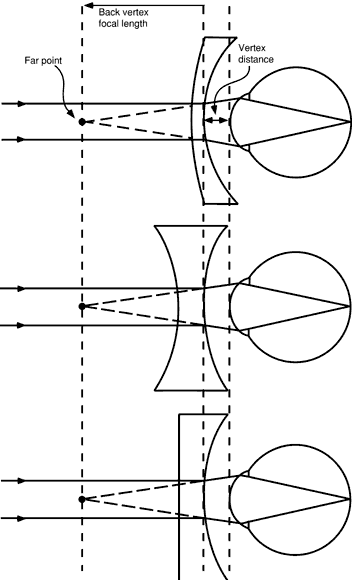
Back vertex power has a number of advantages over other methods used to specify lens powers. Most importantly, back vertex power uses a reference point, the back surface of the lens, whose position can be easily specified using the vertex distance. Second, because back vertex power is specified relative to the position of the back surface of the lens, lenses of any shape (e.g., biconcave, meniscus) can be used to correct a given patient's refractive error, as long as they all have the same back vertex power and are positioned at the same vertex distance (Fig. 7). The back focal point for each lens falls at the same distance from the eye and coincides with the patient's far point, correcting the refractive error. Thus, a patient's refractive error can be measured with refractor lenses or trial lenses that are biconcave, biconvex, plano-convex, or planoconcave in shape, whereas spectacle lenses are prescribed that are meniscus in shape, with no worries about the effect of the shape of the lens on the adequacy of the refractive correction.

Fig. 7. Lenses of different shape but with the same back vertex power will correct a refractive error if each is positioned at the same vertex distance.

In some cases, it is convenient to ignore the effect of thickness on lens power (i.e., to consider the lens to be infinitely thin). Lens power then becomes the sum of the surface powers, and this power is termed the thin lens power or approximate power of a lens. Approximate or thin lens power is used in many of the examples that follow.

MEASURING BACK VERTEX POWER

The instrument used for measuring the back vertex power of a spectacle lens is the focimeter or Lensometer (Reichert Ophthalmic Instruments, a Division of Leica Microsystems, Buffalo, NY). Some focimeters are manually operated, and the operator focuses the instrument to obtain a sharp target image. Others are fully automatic and print out the measured prescription.

Back to Top
THE LENS CLOCK
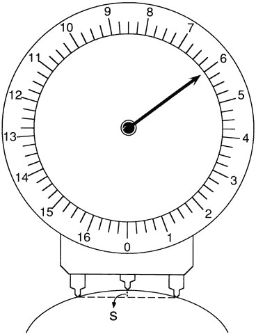
Lens surface powers are measured using a lens clock or lens measure (Fig. 8). When placed against a curved surface, the middle of the three lens clock pegs moves up or down, measuring the sagittal depth of the curve delineated by the two outer pegs. The radius of curvature of the surface is directly related to the sagittal depth. Surface power then is calculated using equation 3. Equation 3 requires that a value for the index of refraction of the lens be chosen, and the value used for all lens clocks is 1.53. Although no lens materials currently available have an index of 1.53, lens clocks are useful in checking and identifying lenses because in the optical industry, the 1.53 values are considered standard.

Fig. 8. A lens clock measures surface power by determining the sagittal depth, S, of a surface. Sagittal depth is converted to surface power using an assumed index of refraction of 1.53.

Back to Top
THE BASE CURVE
The clinician rarely specifies lens surface powers when writing a spectacle prescription because optical laboratory personnel generally choose the surface powers based on the recommendations of lens designers. However, in certain cases, such as when a patient is having trouble adapting to a prescription change or when magnification effects are of concern, the practitioner may have to order a specific surface power or curve as part of the prescription. By convention, the surface power ordered is termed the base curve. The base curve is the reference curve that is the base or basis from which all other surface powers are calculated, and for a single-vision lens it usually is defined as the power of the lens front surface. This base curve is a 1.53 curve, meaning that the base curve will be the value read by the lens clock, not the true surface power. Once the base curve of a lens and the lens power are specified, both of the lens surface powers are completely defined. There can be only one way for the optical laboratory to make the lens.

The base curve of a multifocal lens is defined as the distance portion power or curve on the side of the lens containing the multifocal. Almost all multifocals are on the lens front surface, so the base curve is usually the distance portion power on the lens front surface.

Back to Top
COMPENSATED CURVES
The surface powers of a spectacle lens are not generally specified in the optical industry as the true or exact surface power. Instead, the surface power is changed or compensated for the effects of two other variables. First, as previously mentioned, lens manufacturers and optical laboratories specify the surface powers of all lenses using equation 3, with the index set to 1.53. This practice originated in the early days of spectacle manufacturing, when the index of the glass then in use was approximately 1.53. As time went by and newer materials of many different indices came into use, it was still sensible to keep the same tools for grinding surface powers.

When using 1.53 curves to specify the power of a lens surface, laboratories and lens manufacturers are, in essence, specifying the surface by its radius of curvature. As an example, a lens made of polycarbonate plastic of index 1.586 with a 1.53 base curve of + 5.00 D has a front surface radius, calculated from equation 3 with n2 set equal to 1.53 and n1 set equal to 1, of + 0.106 m. The true front surface power, determined by substituting the true index of refraction into the same formula, along with the calculated lens radius of + 0.106 m, is + 5.53 D.

The practice of specifying exact 1.53 curves for the front curves of spectacle lenses means that manufacturers and optical laboratories can use one set of surfacing tools, standardized to an index of 1.53, to grind the surface curves for all lenses, regardless of lens index. Some manufactures use true power toric tools for the concave side of finished lenses so that cylinder values are precise.

A second compensation of lens surface powers was introduced because the thickness of a lens influences its back vertex power. Before computer use became common in optical laboratories, the 1.53 value of a front base curve was chosen so that a laboratory technician could select a lens blank and know what 1.53 curve to grind on the lens back surface, without a need for difficult calculations. For example, a surfacing chart provided by a lens manufacturer to an optical laboratory might state that a + 4.00 D lens should be made with a + 10.00 D base curve and a -6.00 D back curve. Such a simple calculation of lens surface powers should not work because the calculation seems to ignore both the effect of thickness on power and the use of 1.53 surface curves. However, the lens manufacturer adjusts, or compensates, the base curve of the lens blank from its labeled value so that the simple calculation works accurately. A typical lens thickness is assumed when making the compensation. The actual power of a lens front surface is usually less than its labeled value to compensate for the thickness of the lens.

Today, accurate 1.53 front curves are supplied by the lens manufacturer, and computers are used in the optical laboratory to calculate the thickness and back curves. However, even with computers, unavoidable small errors in lens power occur because the equipment used to grind power onto the lens back surface uses steps of 0.10 or 0.12 D.

Back to Top
SPHEROCYLINDER LENSES
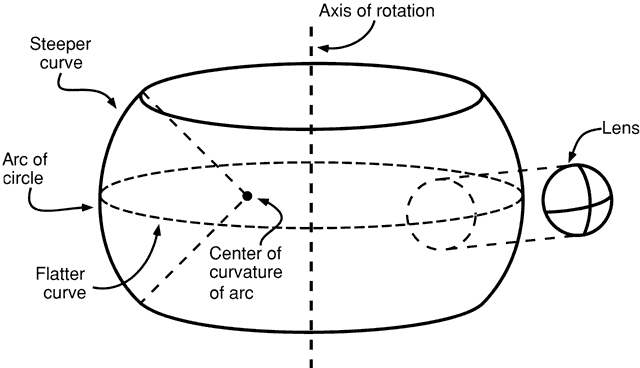
Spherocylinder, or toric, lenses, used to correct astigmatism, have two different powers, one for each principal meridian. These lenses have one spherical surface and one toroidal surface. A toroidal surface has different radii of curvature or different powers in different meridians, with the meridians of maximum and minimum power corresponding to the principal meridians of the lens. The shape of a toroidal surface can be thought of geometrically as the surface obtained by rotating an arc of a circle about an axis (Fig. 9). Depending on the radius of the arc, the figure has somewhat the shape of an automobile tire, a doughnut, or a barrel.

Fig. 9. A toroidal surface, which in this example has the appearance of a tire or doughnut, is generated by rotating an arc of a circle around an axis. The shape of the toric surface of a spherocylinder lens can be thought of as a small section of the toroid.

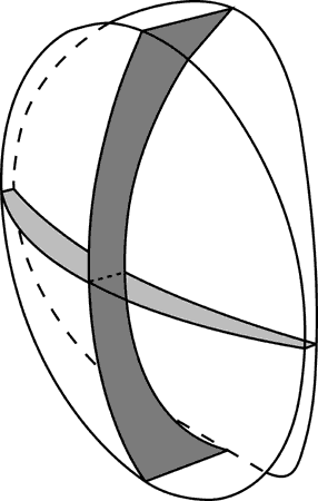
The cross-sectional shapes of a spherocylinder lens in its principal meridians are different (Fig. 10). Light is brought to a separate focus by each principal meridian.

Fig. 10. The cross-sectional shapes of the two principal meridians of a spherocylinder lens are different. Each principal meridian can have either a plus power or a minus power.

PRESCRIPTION NOTATION AND DESIGN OF SPHEROCYLINDER LENSES

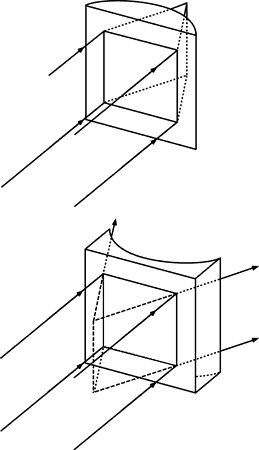
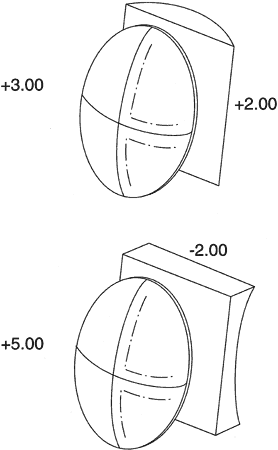
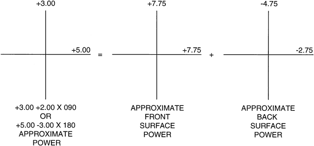
When astigmatic corrections were first used, the corrective lenses were fabricated by cementing a second nonspherical lens onto one of spherical power. These cemented-on lenses were “slices” of a cylinder (Fig. 11). If used alone, a cylinder lens focuses light in only one meridian because the power is in only one principal meridian (the power meridian), the other having 0 or plano power (the axis meridian). The power meridian and cylinder axis are 90 degrees to each other. If a patient needed a + 3.00-D correction in the vertical direction and a + 5.00-D correction in the horizontal, a + 2.00-D cylinder with its axis at 90 degrees could be cemented onto the flat back surface of a + 3.00-D spherical lens, as shown in the upper drawing of Figure 12. Thus, the finished lens had a power of + 3.00 D in the vertical and + 5.00 D in the horizontal direction. It literally was a + 3.00-D sphere combined with a + 2.00-D cylinder. This was the origin of the custom of writing a prescription for astigmatic corrections as a sphere with a cylinder, in this case plus cylinder notation (e.g., + 3.00 sphere + 2.00 cylinder axis 090, abbreviated + 3.00 + 2.00 × 090). The same lens power could have been achieved with a + 5.00-D sphere and a -2.00-D cylinder with its axis horizontal at 0 degrees (see Fig. 12, lower drawing), or as more commonly stated, 180 degrees (+ 5.00 -2.00 × 180). Astigmatic corrections were originally prescribed and fabricated with both plus and minus cylinders. The diagrams of Figure 12 illustrate the concept of what came to be known as a spherocylinder lens.

Fig. 11. Plano-convex and plano-concave cylinder lenses have power in only one meridian. For these examples, the horizontal meridian of each lens focuses light. The vertical meridian of each lens, the cylinder axis, has no refracting power.

Fig. 12. Early astigmatic corrections were produced by cementing spherical and plano-cylinder components.

The next logical step was to grind the spherical and cylindrical powers on one piece of glass instead of cementing two components together. At first, one surface had the entire sphere power and the other was a plano cylinder. As optical manufacturing technology and production methods improved and commonly used lenses became more steeply curved, toric surfaces (with both meridians curved, rather than one plano meridian and one curved meridian) became necessary and available. Currently, nearly all lenses that correct astigmatism have one spherical surface and one toric surface. The toric surface is the back surface for essentially all lenses, so this lens type is termed a minus cylinder design. A patient's lenses are made in minus cylinder design regardless of whether the lens prescription is written in plus-cylinder or minus-cylinder notation.

Figure 13 illustrates, using optical crosses, the surface powers used to make a minus cylinder design lens of power + 3.00 + 2.00 × 090, or + 5.00 -2.00 × 180. The lens has a base curve of + 7.75 D. Many possible combinations of surface powers exist that provide the proper lens power. The surface powers chosen by a lens designer are usually those that provide a lens with the sharpest image across the patient's field of view.

Fig. 13. The surface powers of a spherocylinder spectacle lens are best illustrated using optical crosses. This lens, of power + 3.00 + 2.00 × 090, or + 5.00 -3.00 × 180, is made by the optical laboratory in minus cylinder design. The plus-power front surface is spherical while the minus-power back surface provides the astigmatism correction.

Back to Top
HOW LENSES ARE SUPPLIED
A finished or edged spectacle lens that goes into a patient's frame is made from a lens blank. Optical laboratories buy blanks from lens manufacturers and then perform other operations such as surfacing (grinding the proper power onto a surface of a lens), edging (cutting the lens to the proper shape), tinting, and treating for impact resistance. The following three types of lens blanks are in use.

ROUGH BLANK

Glass lenses are formed by grinding and polishing a molded pressing or rough blank (Fig. 14A). A pressing is a rough, unpolished piece of glass having a meniscus shape, with the surface curves approximating those to be eventually ground on it. Its diameter is that intended for the finished lens. Pressings are usually formed immediately after a gob of molten glass is drawn from the tank where the raw ingredients have been combined. Each gob is pressed between the curved surfaces of a metal mold and allowed to cool. Alternatively, the glass can be drawn from the tank and rolled out into sheets that are cut into lens-sized squares, then shipped. In the molding room of a lens manufacturer, these squares can be reheated and formed into round meniscus-shaped pressings. Optical laboratories rarely use pressings.
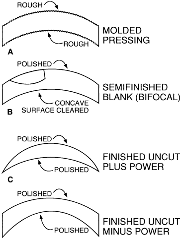
Fig. 14. Lenses are supplied as (A) molded blanks or pressings, (B) semifinished blanks, and (C and D) finished uncut lenses.

SEMIFINISHED BLANKS

A semifinished blank is a lens blank that has been finished on one surface (see Fig. 14B). Glass semifinished blanks are made from a pressing. The pressing is “blocked” or attached to a holding device so that the front surface can be ground and polished to the final power. If the lens is to be a multifocal, a segment or segments must be constructed on the lens front surface. The concave back surface is then given a short grinding and polishing to “clear” the surface. This practice improves the appearance, which is a competitive factor, and also facilitates inspection of the surface and the interior of the glass itself. After inspection, semifinished blanks are packaged and shipped from the lens manufacturer to local optical laboratories through a variety of distribution channels.

The need for a fixed orientation of the multifocal segment prevents rotation of a multifocal lens blank to obtain the proper cylinder axis. Therefore, multifocal lenses are almost universally supplied as semifinished blanks, and the back surface is surfaced by the optical laboratory to obtain the proper lens power and to position the optical center correctly relative to the multifocal segment. Some finished bifocal spheres are available. Single-vision semifinished blanks usually are used only for stronger-than-average lens powers that are not routinely available as uncut lenses.

Plastic semifinished blanks, which are usually multifocal lenses, are made by pouring (CR-39, PPG Industries, Pittsburgh, PA) or injecting (polycarbonate) the plastic into glass or metal molds, then cooling it at a controlled rate. Polycarbonate blanks are then coated for abrasion resistance.

Any one semifinished blank may be used for a variety of prescriptions, depending on what ocular (back) surface power is ground at the local laboratory. A wide range of choices are possible, depending on the thickness of the blank: the thicker the blank, the greater the latitude in curve selection. Prescription accuracy at the optical center and the control of off-axis lens aberrations restrict the choice. One of the objectives of lens design is to design a “set” of these semifinished blanks. This set or series of 10 to 20 lens blanks of different front surface powers and center thicknesses, used in conjunction with a chart of instructions, can provide for hundreds of well-designed but different prescription items. An index of the quality of a series of blanks is their number. Available series number from 4 to approximately 20.

FINISHED UNCUT LENSES

Finished lenses or finished “uncut” lenses have had both surfaces ground to the final optical quality (see Figs. 14C and D). The steps are the same as those described previously, except that thinner pressings or molds can be used because the lens power will not be further modified. The savings in lens material and the lower labor costs of mass production make this a less expensive route than semifinished blanks for popular single-vision prescription items. However, even in this procedure there are economic reasons for using a limited number of surface powers and molds. The uncut single-vision lenses provided by a lens manufacturer should be similar to those made by an optical laboratory from semifinished blanks of the same manufacturer. This provides consistent patient response.

The finished uncut lens must be edged or shaped to fit into a patient's frame. “Layout” for edging includes rotation of the lens to orient the cylinder axis properly and decentration of the lens optical center to position it properly for the patient's interpupillary distance (PD). Glass lenses are further processed after edging to increase impact resistance, whereas plastic lenses may be tinted or coated for abrasion resistance or to reduce reflections. The lenses are then inserted into the frame, and the accuracy of the prescription is verified.

Back to Top